High-capacity bridge cranes—especially those with a lifting capacity of 100 tons or more—are essential for heavy industrial sectors such as steel production, power generation, shipbuilding, and mining. Designing these cranes involves far more complexity than lighter-duty systems. Structural integrity, dynamic load management, safety factors, and operational efficiency must all be meticulously engineered to ensure reliable performance under intense loads.
This article explores the critical aspects of structural design for high-capacity bridge cranes (100t+), covering materials, girder configurations, load considerations, simulation techniques, and real-world implementation strategies.
1. Understanding the Demands of High-Capacity Crane Applications
Unlike small or mid-size overhead cranes, high-capacity 100 ton bridge cranes and above operate in environments where loads often approach the upper limits of structural tolerance. Common applications include:
-
Lifting turbines or generators in power stations
-
Handling ladles of molten metal in steel plants
-
Transferring ship components or large machinery during assembly
-
Moving heavy dies and molds in manufacturing
These tasks require not only lifting strength but also high stability, precise control, and prolonged structural durability under cyclical stress.
2. Key Structural Elements of High-Capacity Bridge Cranes
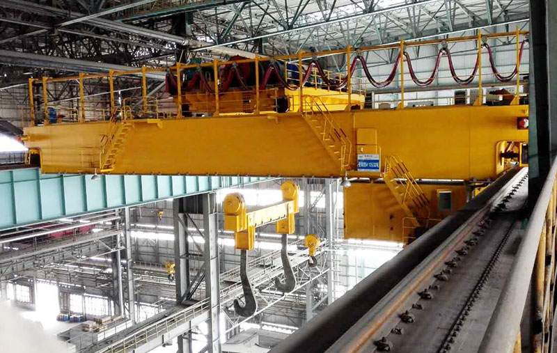
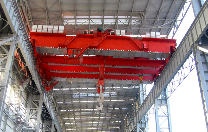
a. Double Girder Configuration
For cranes rated 100 tons and above, double girder bridge crane designs are standard. This setup consists of two horizontal girders supported on both ends by end trucks, distributing load more evenly and enhancing bending resistance.
Advantages include:
-
Greater hook height
-
Higher load capacity
-
Better structural rigidity
b. Box-Type Girders vs. I-Beams
Box-type girders are the most common structural form in high-capacity cranes. These closed-section beams offer excellent torsional resistance and flexural strength, making them ideal for handling massive weights and resisting lateral sway.
In contrast, I-beam girders are generally unsuitable for such high loads due to their open cross-section and lower moment of inertia.
c. End Trucks and Wheels
End trucks must be designed to accommodate extremely high wheel loads. For cranes above 100 tons, multi-wheel configurations (typically 4 to 8 wheels per side) help distribute the load onto the runway beams and reduce floor stress.
High-quality forged wheels and hardened rails are essential to reduce wear and ensure safe rolling under full loads.
3. Material Selection for Structural Integrity
The choice of material is crucial for ensuring long-term performance and safety.
-
High-tensile structural steel (e.g., Q345, S355, ASTM A572) is preferred for girders and end trucks.
-
Special alloy steels may be used in critical joints or high-impact zones.
-
Welding materials must match or exceed the tensile properties of the base metal to prevent stress cracking.
Material certification, traceability, and proper handling procedures (e.g., preheating before welding) are mandatory for structural integrity assurance.
4. Load Calculations and Safety Factors
Designing a 100t+ bridge crane for sale requires precise load calculations, accounting for both static and dynamic forces:
a. Dead Load
Includes the weight of the crane components: girders, trolley, hoist, and accessories.
b. Live Load
This refers to the maximum working load (e.g., 100 tons or more).
c. Dynamic Load Factors
These include the effects of:
-
Hoisting acceleration/deceleration
-
Bridge and trolley travel
-
Load sway and impact forces
Standards such as FEM, CMAA, or ISO provide guidelines for applying dynamic load factors, which often increase the effective design load by 25–40%.
d. Safety Factors
Depending on the duty classification, structural components must meet safety factors ranging from 1.5 to 2.5 times the rated load, especially for critical lifting applications like molten metal handling or nuclear maintenance.
5. Finite Element Analysis (FEA) for Structural Validation
Finite Element Analysis (FEA) is widely used to model stress distribution, deflection patterns, and failure risks in high-capacity crane structures.
Benefits of FEA:
-
Identifies potential weak zones before production
-
Optimizes girder thickness and reinforcements
-
Simulates real-world loading scenarios including wind, seismic, and thermal effects
-
Improves design confidence and regulatory compliance
FEA models are typically run under multiple load cases, and results are validated using physical testing on scaled models or critical sections.
6. Supporting Structural Elements
a. Runway Beams and Columns
The bridge crane structure is only as strong as its support system. For 100t+ cranes, runway beams and supporting columns must be precisely aligned and structurally rated for wheel loads, horizontal forces, and vibration.
b. Buffer and End Stop Design
To absorb kinetic energy and prevent overtravel, end buffers (hydraulic or spring-loaded) are required. These elements must be sized according to the crane’s maximum travel speed and mass.
7. Design for Maintenance and Inspection
Given the criticality of high-capacity double girder eot cranes, structural design must facilitate regular inspections and easy maintenance access:
-
Walkways along girders
-
Maintenance platforms at key equipment points
-
Lifting lugs for replacing large structural elements
-
Built-in fall protection systems
Designers must also accommodate non-destructive testing (NDT) access points in critical weld zones and joints.
8. Seismic and Wind Considerations
In areas prone to seismic activity or high winds, additional structural reinforcements are required:
-
Seismic brackets to anchor the crane in lateral directions
-
Wind girts and bracing to resist uplift and sway
-
Locking devices to prevent uncontrolled movement during storms
9. Modular Construction for Transportation and Installation
Due to their size, 100t+ bridge cranes are often delivered in modular sections:
-
Box girders are split into transportable lengths
-
Field-welded or bolted assembly methods are used
-
Connection points are reinforced and pre-drilled with high-precision templates
This modular approach simplifies logistics and allows for quicker on-site erection with fewer disruptions.
10. Real-World Example
Aicrane recently delivered a 275-ton double girder bridge crane to a power station project. Key structural features included:
-
38-meter span with a box-type girder
-
FEM class A5 for medium-heavy duty
-
Integrated maintenance walkways
-
8-wheel end truck system with hardened wheels
-
Seismic-resistant structure with reinforced joints
The crane is now used for installing generators and turbine shells during the power station’s construction phase.
Conclusion
The structural design of high-capacity bridge cranes (100t+) is a highly specialized field that combines engineering precision, material science, simulation technology, and real-world construction logistics. From girder geometry and material strength to dynamic load handling and seismic safety, every aspect of the structure must be engineered to meet the most rigorous standards.
As industrial lifting demands continue to grow, so too must the sophistication of crane structure design. Partnering with an experienced crane manufacturer ensures not only optimal performance but also long-term reliability and safety.